Windows Project Editor – Manual
1.General
This Manual describes how to use the Windows Project Editor.
This manual can be opened from inside the App or directly using the following link: http://go-to.me/projectedit-manual.
If you prefer a printed version, just tap on the PDF Icon on the website version to download a PDF file.
For some background information about the Windows Project Editor, please read chapter the Background chapter at the end of this Manual.
In case of Bugs, Issues, Questions or Feature Requests, please read this chapter.
2.Overview
For electronic Projects, the main document is the circuit drawing diagram. However, there is much more information in a project that is not contained in the circuit diagram and must be maintained separately. This App keeps everything together.
Besides storing one or more circuits diagrams of a project, it also stores the following information together in a single Project file:
- Component list
- Images
- Documents (such as Datasheets)
- Website links
- Individual notes
3.Project Files
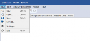
The Project Editor App uses a standard document-based user interface with the usual File New/Open/Save/Save as menus.
Project files are using the extension etb4prj and are fully compatible with Electronic Toolbox and RF-Toolbox for iOS. You can share these files easily with your iOS Apps using iCloud Drive. See “Sharing files with iOS Apps using iCloud Drive” for further information.
4.Working with Tabs
All elements (Items) of a Project is organized under corresponding Tabs in this App.
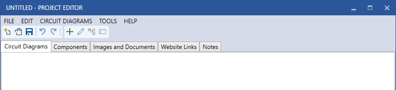
By clicking on the Tap heading (Circuit Diagrams, Components, Images and Documents, Website Links, Notes) you can quickly jump between these sections.
Maintaining the content under each Tab is consistent:
- Add (create) new Items using the Plus Icon (or Menu Add)
- To maintain (Edit) an Item, select the corresponding Item and hit the Pencil Icon (or Menu Edit) or just double-click the Item in the list.
- To remove (delete) a selected Item, use the Delete Icon (or Menu Delete) or the Del-Key on the Keyboard.
- Some Items can be renamed. For this, use the last Textbox Icon (or Menu Rename).
5.Circuit Diagrams and the Circuit Editor
The starting point and main element of a Project is the Circuit diagram. To create a new Circuit Diagram, click on the “Circuit Diagrams” tab, if not already selected and click on the Plus Icon (or use the “CIRCUIT DIAGRAMS” Menu and select “Add…”).
Next you will see an empty Circuit Board.
![]()
The Board has an initial size of 2048 x 2048 points. This can be altered under FILE -> Board Properties.
5.1.Adding Components
To add components to the Board, use the Plus Icon (or the COMPONENT -> Add… Menu). This will open a list of available Components.

Components are grouped by Passive, Active, Input/Output, RF, Power, Gates/Chips and Other.
By clicking on a Group Headline, the corresponding components will be displayed and available for selection.
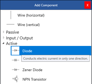
Double-clicking a component on the list will add that component to the Board.

You can then use the mouse to move this component to the right place.
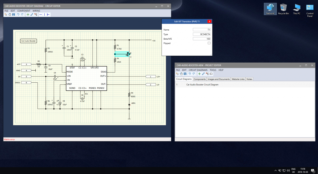
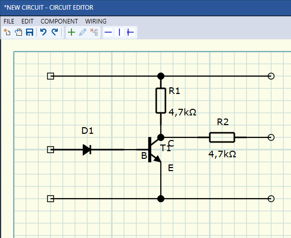
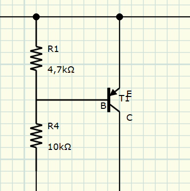
If necessary, for some components such as a Transistor, it is possible to flip pins (e.g. exchange Collector and Emitter). For this, double-click on the component on the Board and check the Flipped box.
Note: If you can’t find the component type you are looking for, see “ Regarding Built in components” at the end of this manual.
Now, you can repeat this step for each of the components you want to place on your board.

Tip: Ideally, after adding the next component, move it to the arbitrary location on the board and don’t add all components one after the other on a single place because then, it’s harder to select and move the right component from the stack of components.
5.2.Wiring components
Once the components were added and are located at the approximate final location, you can wire these components together.
For this, you can place horizontal or vertical Wires from the component selector or from the Icon bar.
Alternatively, you can enable the Wiring mode by hitting the wiring Icon in the Icon bar (or the WIRING -> Wiring mode Menu).
In Wiring Mode, you just draw the Wires by clicking and holding the Mouse at the starting point and releasing the Mouse at the end point of the desired wire. The wire will then be automatically routed. If you are not happy with the result, you can leave the wiring mode and adjust the wires.
In Wiring mode, it is not possible to place crossing wires because the wiring mode always tries to find a way without crossing a wire. For crossing wires, you need to place horizontal or vertical wires manually.
Tip: For complex and narrow placed components, it might be easier if you switch off “Keep components connected” under FILE -> Settings.
5.3.Component properties
Finally, you can maintain the component properties such as the Resistance for Resistors or Type for Transistors, Diodes etc. by double-clicking on the Component itself.
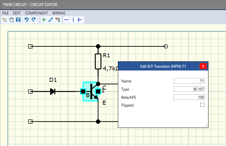
On this Screen, you can also name (or change the name of) the component.
Once that’s finished, you can save the Circuit drawing using the Save Icon or the Menu and close the Circuit Editor using the X Icon or FILE -> Exit Menu.
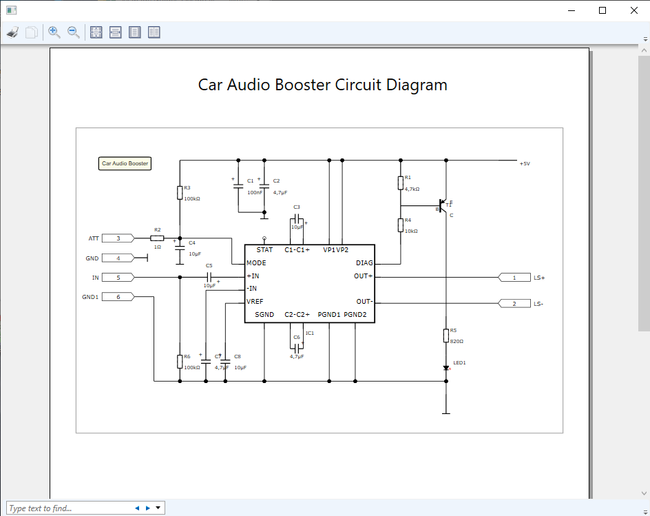
5.4.Printing
Circuit drawings can also be printed. For this, you can adjust the border Size or whether the Circuit should be adjusted to fit on a page by using the FILE -> Print Setup… Menu.
Using FILE -> Print Preview you can see a preview of the printout.
5.5.Board Properties
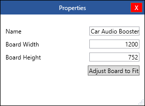
Here you can change the Name of the Circuit Drawing, alter the Board Size or let the Board Size be adjusted to let your Circuit Drawing fit the Board.
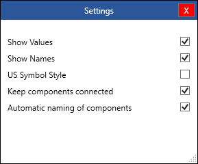
5.6.Settings
Under Settings, you can decide if Values and Names of the Components should be displayed.
If you select US Symbol Style, US Specific Symbols such as the Zig-Zag Resistor Symbol will be used instead of IEC Symbols.
6.Components
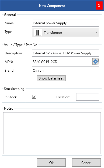
This Components Tab is to maintain Components. This can either be Components for one ore more Circuit Drawings or individual Components, not part of a Circuit.
Besides additional Type information you can maintain additional information such as a flag of whether or not this component is available in your stock and the stock location along with additional notes.
6.1.Components from Circuit Diagrams
Once a Circuit drawing has been finished, all Components will be available under the Components tab.
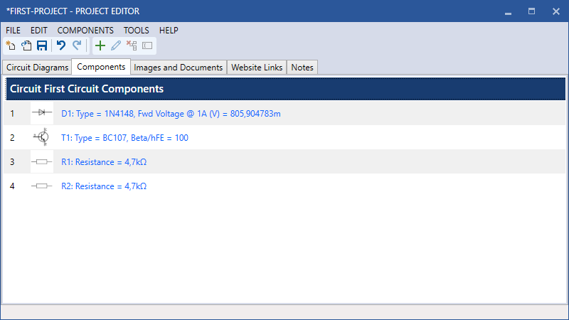
By double-clicking on a component (or selecting the component and using the Pencil Icon or COMPONENTS -> Edit menu) you can maintain additional information for the component.
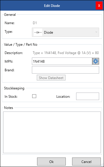
Usually, you want to define the exact component Type (MPN), Brand (Manufacturer) and possibly have a look to the datasheet.
For this, you can use the included Octopart Browser which can be opened using the Gear Icon next to the MPN field.
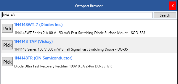
This browser uses the content of the MPN field as search term. If you already entered the Type in the Circuit Editor, this term will be used but you can also enter individual search terms here.
If you can already see the component type you are looking for you can just click on [Pick] to take over the information to the previous component screen.
To see the details of a component, just click on the entry of the list. Next, you can see more detailed information about the selected component. Here you can also view and add various datasheets available for that component.
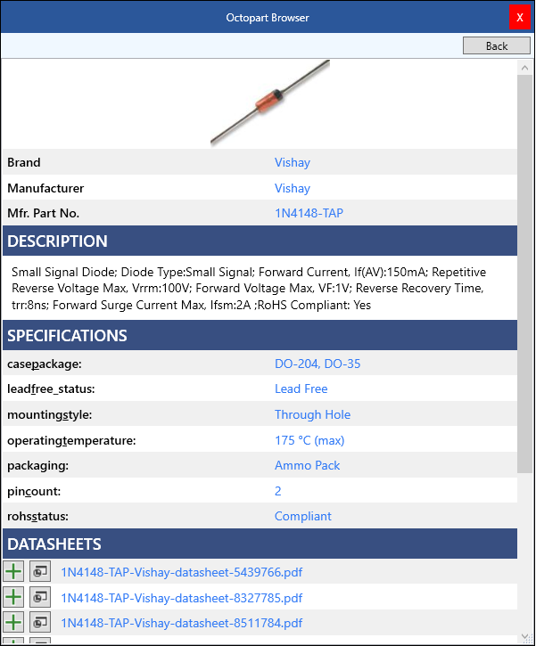
By hitting the Plus Icon, the datasheet will be added to your Project as Document. By hitting the Button next to the Plus, you can preview that datasheet.
If you [Pick] a component, the link to the first datasheet will also automatically be remembered and viewed by hitting the “Show Datasheet” button on the Component details screen.
This way, you can maintain the details for all components of all component of your circuit. If there is more than one Circuit, Components will be separated by each circuit.
Components from Circuit drawings can not be removed, renamed and the Component Type is also fixed. To alter such entries of the Components section, you need to edit the corresponding Circuit Drawing.
6.2.Individual Components
In addition to the components of your Circuit drawings, you can add individual additional components by hitting the Plus Icon (or the COMPONENTS -> Add Menu).
Different to the components from a Circuit drawing, such components can be individually named here, and the component Type and description can be maintained.
7.Images and Documents
If you have used the Octopart Browser to add Datasheets of your components, these Datasheets will end up on this list of the “Images and Documents” Tab.
You can add more Documents by using the Plus Icon (or the DOCUMENTS -> Add Menu) and maintain the list as explained for the other Tabs.
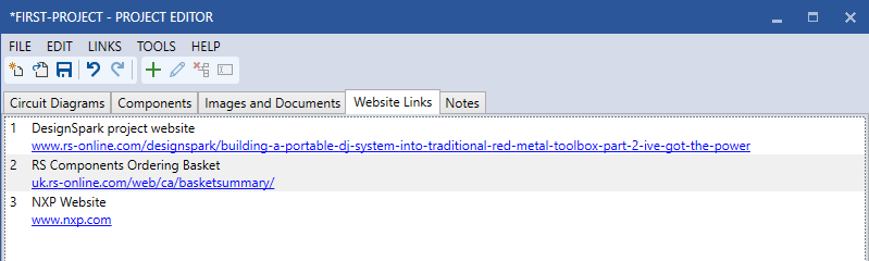
8.Website Links
Similar to Documents, you can maintain a list of Website links. For instance, to Web Forums where your project is being discussed or component ordering websites.
9.Notes
Finally, you can maintain Text notes for your project on the last Tab.
10.Sharing files with iOS Apps using iCloud Drive
Project Files of this Project Editor are fully compatible with Electronic Toolbox and RF-Toolbox for iOS.
You can, of course, exchange project files via Email or other file transfer options with your iOS Apps. However, the most convenient way to access your Project files on both Platforms (Windows and iOS) is by using iCloud Drive.
10.1.iCloud Drive on iOS
For this, you need to enable iCloud AND iCloud Drive on your Apple device. You will find these options under Settings -> Passwords & Accounts and under ACCOUNTS by tapping on iCloud.
Here, you need to enable iCloud in general and iCloud Drive separately further below.
Finally, you need to enable to use iCloud Drive in Electronic Toolbox or RF-Toolbox in the App Settings under Miscellaneous.
Once you open the iOS Project Editor under Make, you will see all Project files located on your iCloud Drive.
10.2.iCloud Drive on Windows
Even though it would also be possible to access your iCloud Drive Projects using a standard Browser (https://icloud.com) it is more useful to install Apples iCloud Drive Software on your Windows PC.
More information to the Setup and the download link of the iCloud Software can be found here:
https://support.apple.com/en-us/HT201391
It is sufficient to just enable iCloud Drive for sharing Project Files with your iOS Apps. Other features like sharing Photos, Email etc. doesn’t need to be enabled.
After the Software has been installed, you will see a new iCloud Drive folder in Windows File-manager. The Subfolder Projects is where the iOS Apps are storing their Project Files.
If you don’t see these Folders, just start the iOS App, create and save a Project. It may take some time until this document has been Synchronized the first time. Further Synchronizations are much faster.
You can copy this Project Path as default Project File Folder for the Windows Project Editor App under Settings.
Now, you can conveniently Start a Project on one platform and continue to work on the Project on another Platform.
11.Settings
Under “Settings…” you can enter the preferred path where to open or save your projects.
If you are also using Electronic Toolbox or RF-Toolbox for iOS, you can enter the path to your iCloud Drive and share Project files via iCloud Drive with your iOS Apps.
If you prefer to use an external Document Viewer for opening PDF-, Image- or other Document files from inside Project Editor, just tick the “Use external Document Viewer” box.
12.Additional Notes
12.1.Regarding built in components
Even though, there are more than 80 different component types available, you may need a component type which is not available in this App.
In this case, you can either use a component which closest matches the component you are looking for and enter a corresponding type name. Or you can use the General IC Component where you can maintain any number and names for Pins. For this, just add the Chips -> IC Component to your circuit and alter the Pins in the Component properties box after double-clicking on the component.
Here, you can enter Pin Names for all four sides of the Symbol, separated by comma.
If you need more space between pins (e.g. due to a larger Pin name), just leave a Pin name blank by just entering another comma.
13.Background
Some years ago, a user of my App Electronic Toolbox asked me to add a Circuit drawing Tool for my App. I first was a bit reluctant for this idea as I didn’t believe that an iPad (not talking about an iPhone) is the ideal device for drawing Circuits. The lack of space (even on an iPad Pro) and the lack of a mouse with it’s pointer, hover and right-click possibilities will make it hard to draw Circuits on an iOS Device, even when using the Apple Pencil.
However, over time, more and more people asked for this so I started developing a Circuit Drawing Tool for my App. After several months of development time I found some of my assumptions confirmed but also found the Drawing Tool is better than anticipated. I finally ended up using it quite a lot for quick and simple drawings.
The Circuit Drawing Tool as well as the Project Tool have been improved over time. The Drawing Tool now Synchronizes Components seamlessly, in the Background with more than one Circuit and there is now a Cross Reference and Order List Tool and it is possibility to order Components directly from RS-Components.
Due to these improvements, I was using my Tools more and more often and almost discontinued using other standard software but then I realized that I started indeed missing a mouse and a larger screen.
That’s why I started developing the Windows Project Editor early 2018 and it’s now finally available.
My goal was to have a Project Editor that is fully compatible with the iOS Project Tool of Electronic Toolbox and RF-Toolbox. For this, I had to add a few features to the iOS Version such as the General IC which can be used to draw any IC even if it is not included in the component list. Now it is possible to start a Project on the iPad and continue on a PC (or vice verse).
I intentionally developed this Project Editor as Windows Desktop App and not as Universal Windows App (UWP) or Mac App. The reason is, Universal Apps are basically Tablet Apps which can run on Desktop PCs, feel a bit like Desktop Apps but have a lot of limitations like limited Mouse support and the restriction on a single window.
Even though I have a fantastic 5K 27″ iMac and a MacBook Pro 2018 which I think is the best Laptop available today, I am maintaining all my Electronic Files, Research and Software on my PC. The same is true for all my HAM Radio activities. I assume, with legitimate and honorable exceptions, most people are doing the same so I didn’t consider a MacOs App.
14.In case of Bugs, Issues, Questions or Feature Requests
As mentioned, I am using this App myself so every bug is painful for myself.But sometimes I might not even notice or run into a bug which happens on your end.
So in case you find a bug, have other issues questions or just want to suggest new features, please don’t hesitate and let me know. This will not only help me and you, it will also help all others as I want to fix any possible bug and improve the App as best as possible.
Ideally, use Menu inside the App. Like all my Apps, Project Editor has a “Support or Feature Request” menu which can be found under “HELP”.
Alternatively, use the Form on my Website.
Thank you!
Marcus